Product code: H13
Normal Qty Required: 1
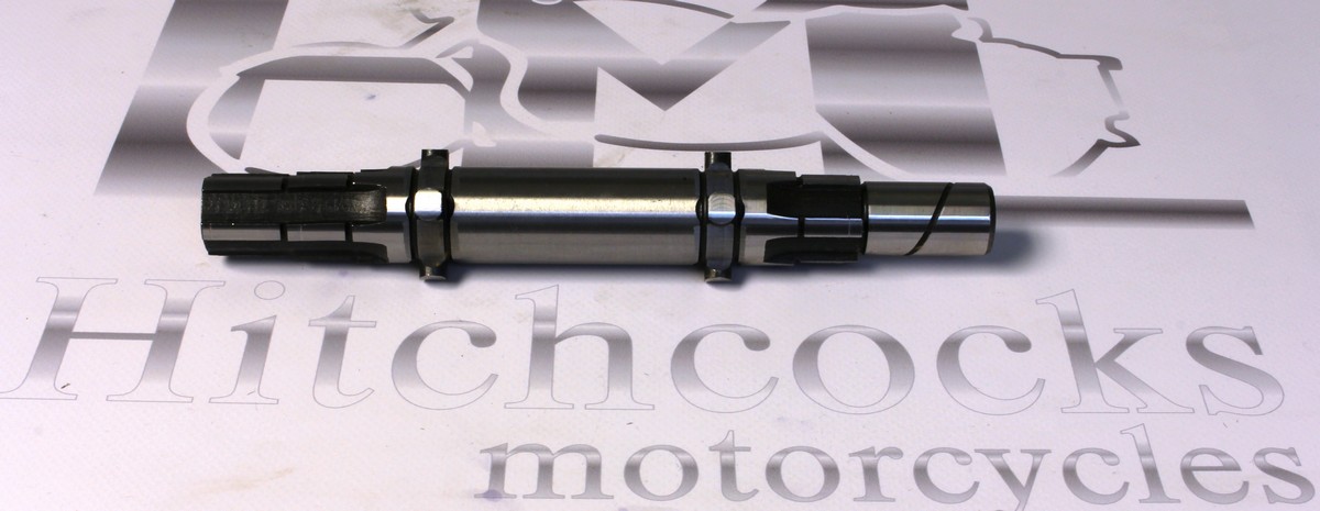
LAYSHAFT
LAYSHAFT

Product code: H14
Normal Qty Required: 1
BUSH, LAYSHAFT (CASE END), 4SPEED
LAYSHAFT BUSH (CASE END)

Product code: H15
Normal Qty Required: 1
BUSH, LAYSHAFT ( KICKSTART INNER), 4 SPEED
KICKSTART INNER BUSH

Product code: H16
Normal Qty Required: 1
BUSH, LAYSHAFT, SPLINED
LAYSHAFT SPLINED BUSH

Product code: H17/18
Normal Qty Required: 1
GEAR, LAYSHAFT LOW 18T (With shoulder)
GEAR, LAYSHAFT LOW 18T

Product code: H18/23
Normal Qty Required: 1
GEAR, LAYSHAFT, SECOND,23T
GEAR, LAYSHAFT 2nd 23t

Product code: H19/27
Normal Qty Required: 1
GEAR, LAYSHAFT, THIRD, 27T **Used** Condition 6/10
GEAR, LAYSHAFT THIRD 27T
Product code: H20/30
Normal Qty Required: 1
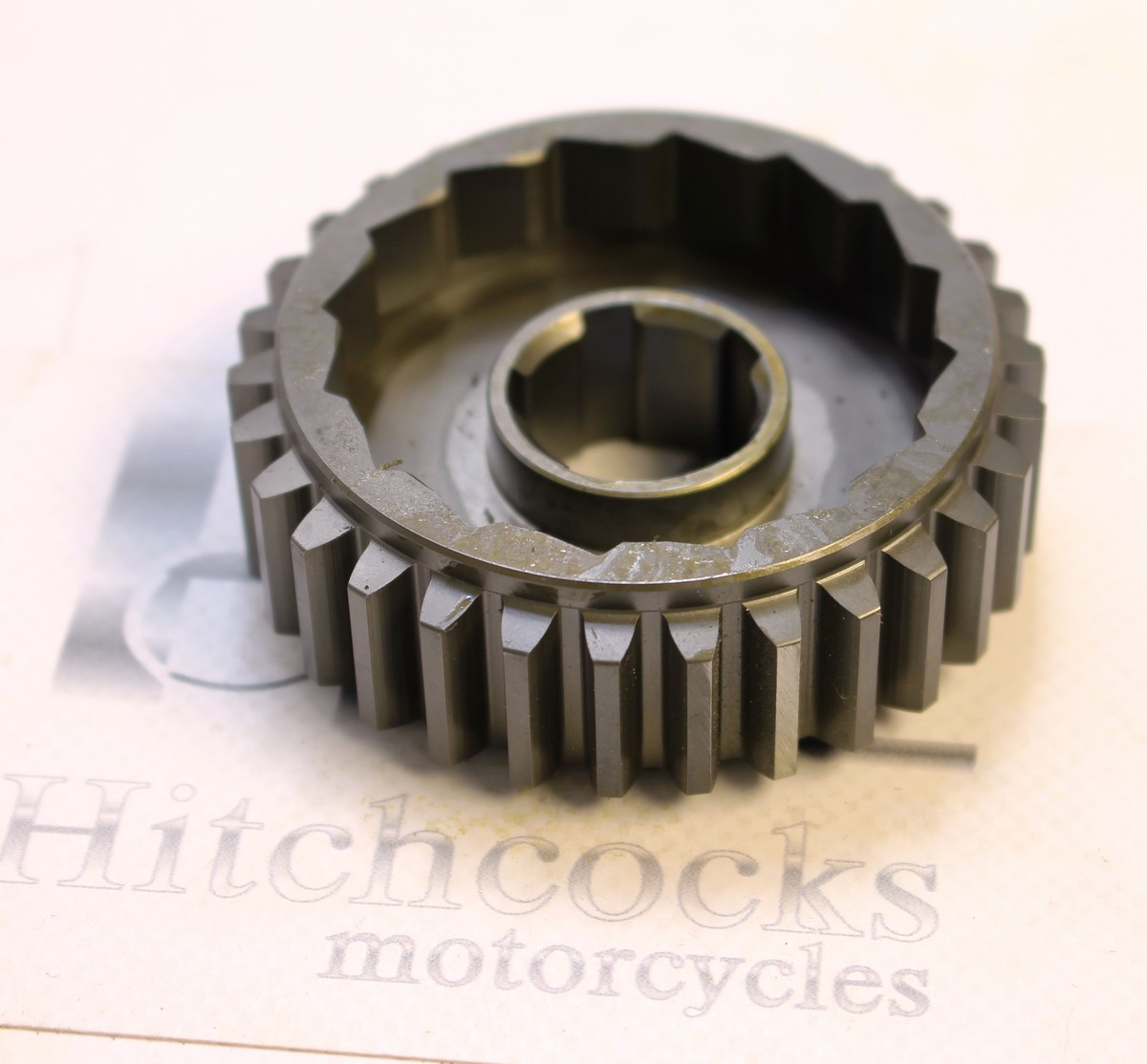
GEAR, LAYSHAFT, HIGH/KICKSTART WHEEL, 30T
GEAR, KICKSTART WHEEL 30T
Product code: 37354
Normal Qty Required: 1
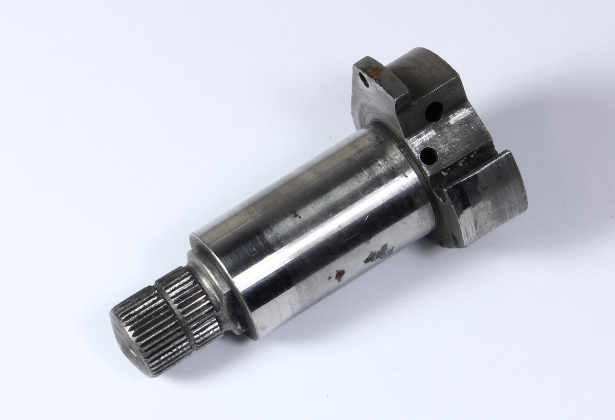
KICKSTART SPINDLE, Splined type with 1 bolt fixing pawl stop (1951-54 G, J, G2 + Twin etc) **USED** CONDITION 6/10
KICKSTART SPINDLE

Product code: H22
Normal Qty Required: 1
EARLY KICKSTART PAWL
EARLY KICKSTART PAWL
Product code: H22A
Normal Qty Required: 1
PLUNGER, KICKSTARTER PAWL
KICKSTART PLUNGER

Product code: H23
Normal Qty Required: 1
SPRING, KICKSTART PAWL PLUNGER
K/S PAWL PLUNGER SPRING

Product code: 37356
Normal Qty Required: 1
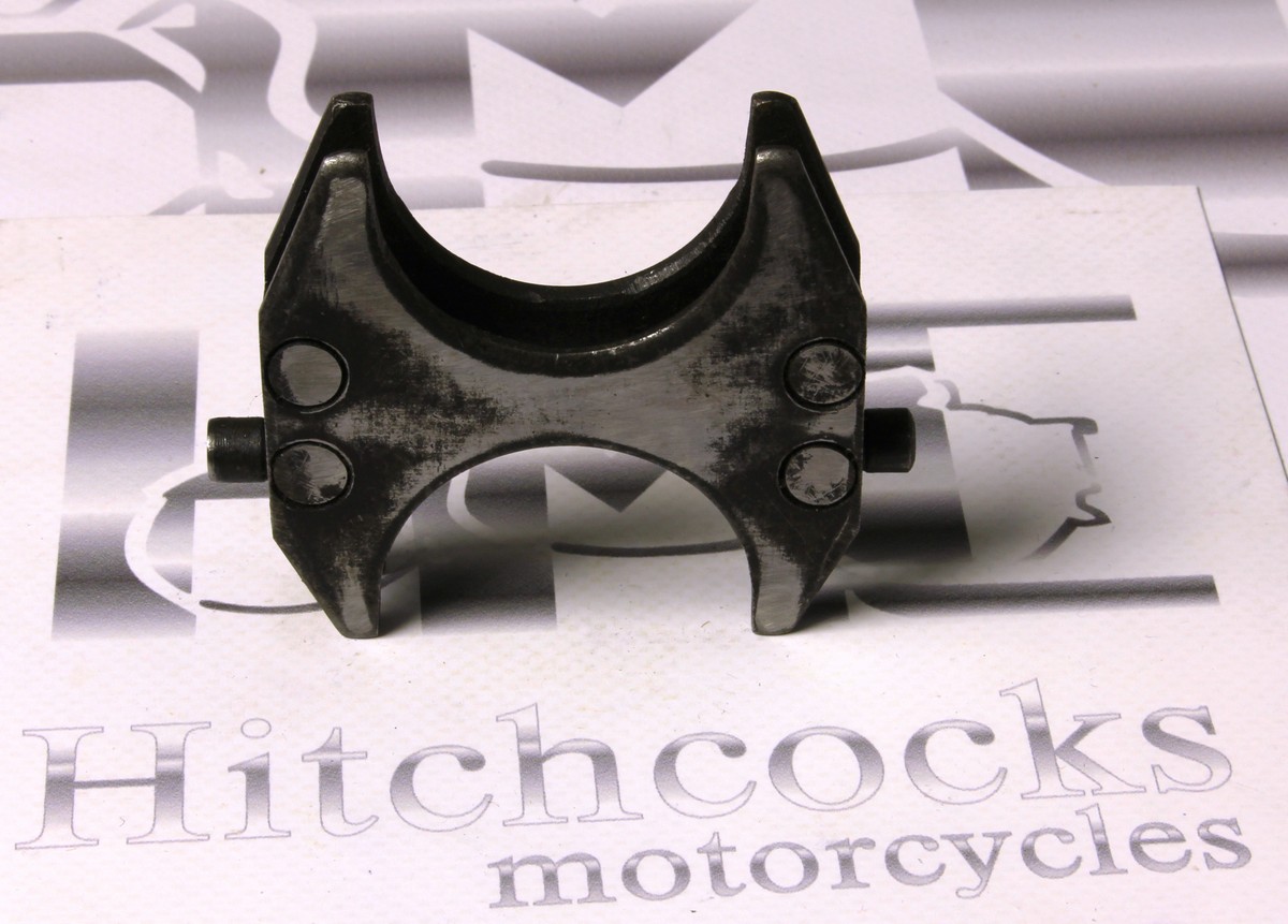
STOP PLATE WITH BOLT, KICKSTART SPINDLE
STOP PLATE

Product code: 37357
Normal Qty Required: 2
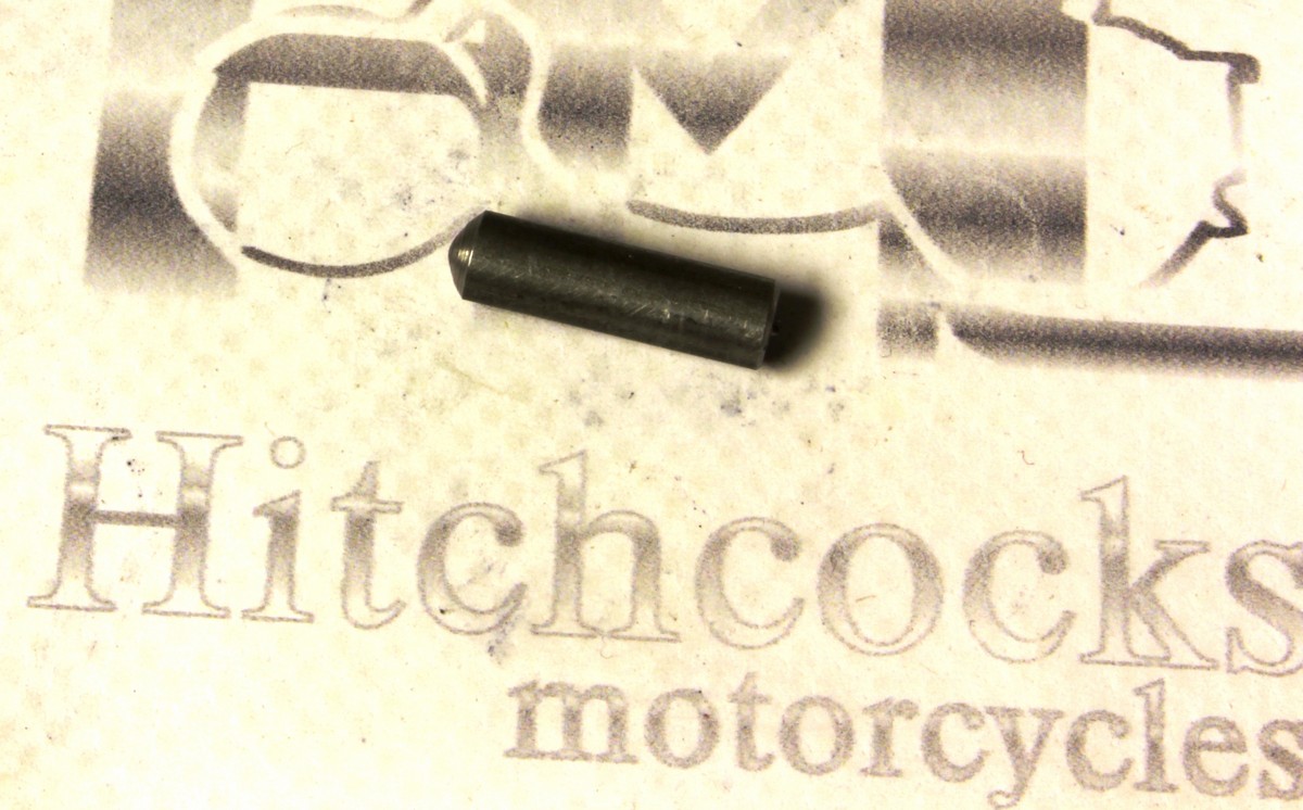
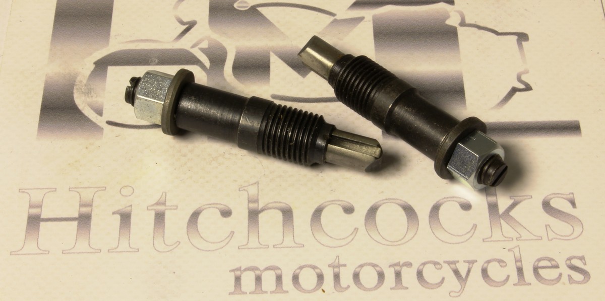
STOP BOLT, FOOTSTARTER PAWL
FOOTSTARTER PAWL STOP BOLT

Product code: H27
Normal Qty Required: 1
BUSH, OUTER, KICKSTART
KICKSTART OUTER BUSH

Product code: H28
Normal Qty Required: 1
SPRING, KICKSTART
KICKSTART SPRING

Product code: H29
Normal Qty Required: 1
CUP, KICKSTART, STAINLESS
KICKSTART CUP

Product code: 112024
Normal Qty Required: 1
KICKSTART LEVER ASSY COMPLETE WITH RUBBER, FOLDING
FOLDING KICKSTART Complete with pedal (INDIAN MADE ALTERNATIVE)

Product code: H42/42A/6
Normal Qty Required: 1
KICKSTART COMPLETE WITH RUBBER AND PINCH BOLT (FOLDING), Approx 2cm throw-out. UK Chromed
FOLDING KICKSTART Complete with pedal

Product code: H42/42A/S
Normal Qty Required: 1
KICKSTART, NON FOLDING
KICKSTART, NON FOLDING

Product code: H43/5
Normal Qty Required: 1
KICKSTART PINCH BOLT AND NUT
BOLT AND NUT
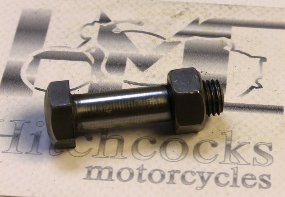
Product code: H43/5S
Normal Qty Required: 1
*STAINLESS* KICKSTART PINCH BOLT AND NUT
** ALTERNATIVE (STAINLESS) **

Product code: H33
Normal Qty Required: 1
GEAR OPERATOR, INSIDE
GEAR OPERATOR, INSIDE
Product code: H34
Normal Qty Required: 1
GEAR SELECTOR FORK
GEAR SELECTOR FORK

Product code: G2/36
Normal Qty Required: 1
GEAR OPERATING PIN (Pre 1959, slotted, approx 96mm long)
GEAR OPERATOR PIN

Product code: G2/37
Normal Qty Required: 1
BUSH, GEAR OPERATOR PIN (Outer thread 7/16" x 20tpi cycle)
PIN BUSH


Product code: H63
Normal Qty Required: 1
SPRING, GEAR BOX PLUNGER
GEAR BOX PLUNGER SPRING
Product code: H61A
Normal Qty Required: 1
PLUNGER ASSEMBLY c/w nut and washer (new design)
PLUNGER ASSEMBLY, REPLACES ITEMS 25, 26 AND 27

Product code: 111189
Normal Qty Required: 1
SPROCKET, 17 TEETH, GEARBOX, 4 SPEED, INDIAN MADE (UP TO 2B5 11911A)
SPROCKET 17T, INDIAN MADE

Product code: H49/17
Normal Qty Required: 1
SPROCKET 17T, 4 SPEED, UK MADE (also Indian copy 111189)
SPROCKET 17T, UK MADE

Product code: H120
Normal Qty Required: 1
NUT, FINAL DRIVE SPROCKET Approx 12mm overall length
FINAL DRIVE NUT

Product code: H121
Normal Qty Required: 1
FELT, FINAL DRIVE SPROCKET NUT
FINAL DRIVE SPROCKET NUT FELT

Product code: H122
Normal Qty Required: 1
GRUB SCREW, G/BOX SPROCKET (CAN USE 111161)
GEARBOX SPROCKET GRUB SCREW

Product code: 33887
Normal Qty Required: 1
FOOTCHANGE COVER, EARLY (USED) NO DAMAGE AND GOOD THREADS.
FOOTCHANGE COVER, EARLY **used**
Product code: H15A
Normal Qty Required: 1
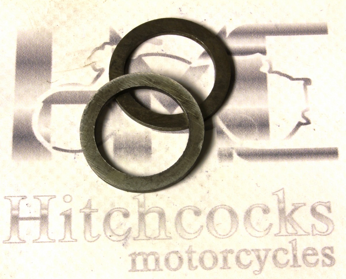
KICKSTART SPINDLE WASHER, (H21A)
KICKSTART SPINDLE WASHER, (H21A)

Product code: G2/53
Normal Qty Required: 1
SPACER, GEARBOX MAIN SEAL
GEARBOX SPACER
Shop for accessories at Hitchcocks Motorcycles